|
||
| Sulphuric Acid on the WebTM | Technical Manual | DKL Engineering, Inc. |
Knowledge for the
Sulphuric Acid Industry
![]()
Sulphuric Acid on the Web
Introduction
General
Equipment Suppliers
Contractor
Instrumentation
Industry News
Maintenance
Acid
Traders
Organizations
Fabricators
Conferences
Used
Plants
Intellectual
Propoerty
Acid
Plant Database
Market
Information
Library
Technical Manual
Introduction
General
Definitions
Instrumentation
Plant Safety
Metallurgial
Processes
Metallurgical
Sulphur Burning
Acid Regeneration
Lead Chamber
Technology
Gas Cleaning
Contact
Strong Acid
Acid Storage
Loading/Unloading
Transportation
Sulphur
Systems
Liquid SO2
Boiler Feed Water
Steam Systems
Cooling Water
Effluent Treatment
Utilities
Construction
Maintenance
Inspection
Analytical Procedures
Materials of Construction
Corrosion
Properties
Vendor Data
DKL Engineering, Inc.
Handbook of Sulphuric Acid Manufacturing
Order
Form
Preface
Contents
Feedback
Sulphuric Acid
Decolourization
Order Form
Preface
Table of Contents
Process Engineering Data Sheets - PEDS
Order
Form
Table of Contents
Introduction
Bibliography of Sulphuric Acid Technology
Order Form
Preface
Contents


Steam Systems -
Commissioning - Steam Blows
April 25, 2004
Introduction
 The
purpose of blowing the steam lines prior to starting up a new unit is to remove
any foreign matter remaining in the equipment (i.e. superheater) and steam
piping after erection is completed. Considerable damage could result if
such foreign matter was allowed to enter the plant steam system during initial
operation.
The
purpose of blowing the steam lines prior to starting up a new unit is to remove
any foreign matter remaining in the equipment (i.e. superheater) and steam
piping after erection is completed. Considerable damage could result if
such foreign matter was allowed to enter the plant steam system during initial
operation.
On older units the need for steam line blowing should be considered following
major pressure parts repairs, where the possibility of introduction of foreign
material into the system exists.
Since prevention of damage to the plant steam system is the prime concern, the
responsibility for determining the effectiveness of the steam line blowing
operation rests with the plant operator. During the steam line blowing
process the unit should be operated in accordance with the vendor recommended
procedures, with all control systems and protective interlocks functioning.
The principle behind steam blowing lines clean is that the thermal cycling
(heating/cooling) and high velocity gas flowing through the line will "shock"
the pipe and tend to break the mill scale and weld slag away from the pipe wall.
Ideally, steam blowing should be done prior to the system being insulated to
maximum the thermal cycling of the equipment. If the system is insulated,
a greater time between blows may be necessary to allow the system to cool.
Ideally, to obtain optimum cleaning, the flow conditions in the system during
steam line blowing should equal those during normal operation at maximum load.
Since it is impossible to exactly duplicate these conditions when blowing
through the piping to atmosphere, it is desirable to produce equivalent
conditions by using lower pressure steam with a flow rate such that the product
of steam flow times velocity will equal that under normal full load conditions.
The determination of the total obtainable flow quantity must be based on flow
resistance in the entire system, including the temporary piping. This
determination is normally made by the designer of the blowing system.
The temporary piping is normally equipped with a shutoff valve that is used as a
blowing valve. With this arrangement, the superheater and the upstream
portion of the temporary piping are maintained at drum pressure at all times
when not actually blowing.
Note: If the unit is equipped with a main steam stop valve, this may be used as a blowing valve, if the valve design permits this type of service.
An indication of the cleanliness is obtained by impact specimens, installed in
the blowoff piping during the final blows. Suitably mounted and supported,
polished square bar stock has been effectively used for this purpose. The
degree of pitting of the specimen surface following a blow is used to determine
the end point of the blowing cycle.
This procedure is general in nature and as such should be adapted to the specific conditions and procedures existing at the site at the time the operation is performed.
Safety
The process or steam blowing imposes abnormal and severe conditions upon the
boiler, steam equipment and steam piping. Large, rapid temperature changes
occur during each blowing cycle. This cycling of temperature is far more
severe than is incurred in normal operation. Thermal stresses may be
excessive in the heavy wall portions of the system such as steam drums, headers
and piping. It is prudent to consider this fact when performing the
blowing procedure and to limit the number of blows to the minimum consistent
with cleaning the system.
Since the temporary steam blowing piping may be designed for lower pressure than
the boiler, care must be used to prevent over pressuring this piping during the
entire steam line blowing operation. The pressure in the temporary piping
should be monitored continuously and operators be alert to prevent over
pressure.
It is recommended that a means of over pressure protection be provided in the
temporary piping, such as, safety valves set at the design pressure of the
temporary piping.
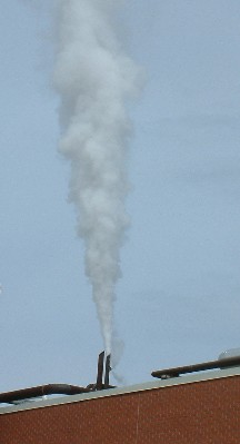
Noise levels will be very high during the steam blow. Hearing protection
is mandatory for those in the immediate vicinity of the steam outlet. An
area at least 100 m from the blow point must be roped off to prevent personnel
from approaching too close.
Equipment and Supplies
The following equipment will be required:
Material: St 37 or ASTM A36 or ASTM A516 Gr 70
Hardness: 140 - 160 HB
Procedure
The unit is started in the normal manner. All normal recommendations and
limitations with respect to fuel firing equipment, air handling equipment,
drains and vents, etc., should be followed, as if the unit were being started
for normal operation. As for any new unit, the steam blowing
operation is the first occasion that the unit is fired at any significant rate.
Consequently, the startup as well as the steam line blowing must be conducted
with great care. The normal startup rate does not apply; the unit must be
brought up much slower, while all equipment is checked and expansion movements
monitored closely. If the unit is equipped with a fired superheater, the
1000°F (538°C) furnace exit gas temperature limitation must not be exceeded when
the unit is fired. The same general precautions taken on any new unit for
this period of operation apply equally here.
The drum level will be subject to extreme fluctuations during the blows.
As the temporary blowoff valve is opened, the drum level will rise rapidly and
may go out of sight in the gauge glass. As the blow progresses the drum
water level will re-appear and may drop out of sight. Therefore, it is
important that the drum level is established at or slightly above normal
operating level before the start of each blow. A small amount of
feedwater flow should be established before the start of each blow and the
feedwater flow should be increased as soon as the water level drops back in
sight, in order to prevent excessive low water level.
When the drum pressure reaches the value calculated to produce the desired
blowing flow quantity, the blowing procedure can be started.
It is difficult to avoid
carryover from the steam drum to the superheater during the steam line blowing
operation. Therefore, boiler water should not be treated with non-volatile
chemicals during this process, to avoid deposits of solid materials into the
superheater.
Firing of all fuels must be discontinued during all blows.
General Pre-Cleaning Procedures
1. Check all pipe anchors and guides for adequate support of
piping, including the temporary vent pipe.
2. Insure that all lines have been inspected and hydrotested.
3. Remove all control valves, desuperheater nozzles, flow elements,
thermowells, pressure gauges, orifice plates, safety valves and instruments that
may be damaged during the steam blow.
4. Insure all vent pipes have adequate drains and that these
drains are routed to a safe location.
5. Install temporary pressure gauges as required to monitor
the progress of the steam blow and make arrangements for to record pressure
readings.
6. Establish adequate radio communication between the control room
and the operator at the shutoff valve. Back this up with a system of
visual communication, such as lights or flags, since audio communication may be
difficult due to high noise levels at the steam shutoff valve.
7. Insure personnel traffic is controlled in area during steam blow.
Insure the area near the vent pipe is clear of all personnel during the steam
blow. Protect neighbouring equipment from damage due to the steam vents.
8. Individuals operating the steam blow valves (especially near the
vent pipe) should wear double ear protection.
General Cleaning Procedure
1. Discontinue all firing and gradually open the temporary
blowoff valve, to blow through the steam system and out the temporary blowoff
piping.
Caution: The first blow should always be done at reduced pressure, in order to check out the temporary piping system, its supports and anchors.
2. When the drum pressure has dropped to the value
corresponding with a 100°F (56°C) saturated steam temperature decrease, close
the temporary blowoff valve and refire the unit to re-establish blowing
conditions.
3. Repeat the above cycle until it is considered that cleaning
is satisfactory as indicated by inspection of impact specimens during the final
blows.
1. Drain the temporary and permanent piping.
2. Remove temporary spools, blind flanges, temporary vent piping, etc., and reinstall all components removed prior to steam blow.
Cleanliness Criteria
The turbo-generator vendor or the primary end user of the steam will generally specify the criteria to which the system should be cleaned. If steam is used in a turbo-generator the following criteria is generally used:
Criteria
- No indentation exceeding 0.8 mm diameter
- Indentation exceeding 0.4 mm diameter to number not more than 2 per 2500 mm² of the target plate surface
- Indentations exceeding 0.2 mm to number not more than 10 per 2500 mm² of the target plate surface
- Indentations less than 0.2 mm to be well dispersed and nowhere present in concentration