|
||
| Sulphuric Acid on the WebTM | Technical Manual | DKL Engineering, Inc. |
Knowledge for the
Sulphuric Acid Industry
![]()
Sulphuric Acid on the Web
Introduction
General
Equipment Suppliers
Contractor
Instrumentation
Industry News
Maintenance
Acid
Traders
Organizations
Fabricators
Conferences
Used
Plants
Intellectual
Propoerty
Acid
Plant Database
Market
Information
Library
Technical Manual
Introduction
General
Definitions
Instrumentation
Plant Safety
Metallurgial
Processes
Metallurgical
Sulphur Burning
Acid Regeneration
Lead Chamber
Technology
Gas Cleaning
Contact
Strong Acid
Acid Storage
Loading/Unloading
Transportation
Sulphur
Systems
Liquid SO2
Boiler Feed Water
Steam Systems
Cooling Water
Effluent Treatment
Utilities
Construction
Maintenance
Inspection
Analytical Procedures
Materials of Construction
Corrosion
Properties
Vendor Data
DKL Engineering, Inc.
Handbook of Sulphuric Acid Manufacturing
Order
Form
Preface
Contents
Feedback
Sulphuric Acid
Decolourization
Order Form
Preface
Table of Contents
Process Engineering Data Sheets - PEDS
Order
Form
Table of Contents
Introduction
Bibliography of Sulphuric Acid Technology
Order Form
Preface
Contents


Technology - NOx
July 5, 2003
|
Introduction Treatment Gas Phase Treatment Liquid Phase Treatment Case Study - INCO References |
Associated Links |
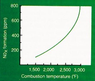
The trend to smelting processes utilizing oxygen enrichment has resulting in more energy efficient smelting operations, higher throughputs and smaller downstream gas handling equipment. Higher smelter operating temperatures result from the smaller quantity of nitrogen present in the gas which acted as a heat sink. The higher operating temperatures result in an increase in nitrogen fixation according to the following reactions:
N2 + O2 <-> 2NO
2NO + O2 <-> 2NO2
|
Thermal NOx Formation |
Nitrogen oxides formed in this manner are referred to as thermal NOx. In addition to temperature, the formation of NOx is governed by residence time and oxygen concentration. High temperatures favour the formation of nitrogen monoxide (NO) but as the gas cools, NO2 is formed. Increasing residence time and oxygen will also result in the formation of more NOx. The majority of the nitrogen oxides present in the gas will be the result of thermal NOx.
Nitrogen oxides may also be present in the fuel that is used in the smelter to maintain operating temperatures. The combustion of the fuel leads to the formation of chemical NOx.
A third source of nitrogen oxides results from the operation of the wet electrostatic precipitators (WESP’s). Electrical arcing in the WESP’s causes the formation of nitrogen oxides.
The nitrogen oxides pass from the smelter into the downstream acid plant where it ultimately contaminates the product acid. NO is insoluble in sulphuric acid so no NO enters the acid through the Drying Tower. Instead, NO is further oxidized by the oxygen in the gas according to the following reaction:
2NO + O2
<->
2NO2
This reaction occurs rapidly in the catalyst beds.
NO and NO2 in equal molar proportions behaves as N2O3 which is readily soluble in sulphuric acid:
NO + NO2 + 2H2SO4 <-> 2NO•HSO4 + H2O
or
N2O3 + 2H2SO4 <-> 2NO•HSO4 + H2O
Nitrosylsulphuric acid (NO•HSO4) is the dominant nitrogen-containing species that contaminates the acid and is commonly referred to as ‘nitrates’.
The nitrogen oxides in the gas are preferential absorbed by the submircon acid mist particles which have a high surface area to volume ratio. Thus, most of the nitrates present in the acid plant are concentrated in the acid draining from the high efficiency candle mist eliminators.
Nitrates in the acid accelerates corrosion of steel equipment and discolours the acid reducing the quality of the acid. Some acid consumers require low or zero nitrate levels in the acid. If nitrates are present in acid used in the sulphonation process, a reaction will occur with the benzene ring to produce a greenish black slurry.
If Fe+2
is present, the acid will appear pink in colour.
The following reaction occurs:
2FeSO4 + HNO3 + H2SO4 -> HNO2 + Fe2(SO4)3 + H2O
The pink colour is probably caused when N2O3 is dissolved in sulphuric acid and NO+ is formed which reacts with Fe2+ to form a co-ordination complex. Aerating or heating the acid will oxidize HNO2 to HNO3 which breaks the co-ordination complex causing the pink colour to disappear. Unfortunately, the reaction is reversible and the pink colour will return.
The nitrate problem in an acid plant can be treated either in the gas phase or the liquid phase. The quantity of nitrogen oxides formed in the smelter can be minimized by ensuring the process operates steadily and minimizing local hot spots in the furnace, however, the formation of NOx cannot be totally eliminated.
Treating the NOx as far upstream in the process is the most desirable route for any contaminate. Treatment of NOx in the gas phase involves reducing the nitrogen oxides to nitrogen gas. In other industries, NOx is treated in the gas phase by Selective Catalytic Reduction (SCR), Selective Non-Catalytic Reduction (SNCR) and various scrubber technologies.
The SCR process involves the reaction of NO and NO2 with ammonia or urea in the presence of a catalyst to form nitrogen and water.
4NO + 4NH3 + O2 -> 4 N2 + 6H2O
6NO2 + 8NH3 -> N2 + 12H2O
Excess ammonia will react with oxygen to ultimately form nitrogen and water.
4NH3 + 5O2 -> 4NO + 6H2O
4NH3 + 3O2 -> 2N2 + 6H2O
The reaction occurs in the presence of the catalyst at a temperature between 300°C and 425°C. The ideal location for the treatment of NOx by SCR is immediately prior to the first catalyst pass which is well upstream of the point where NOx will enter the acid system. The operating temperature at this location falls into the operating range of the SCR catalyst so no additional heat or cooling of the process gas is required. As well, no SO3 is present which would react with ammonia to produce ammonia sulphate.
In addition to nitrogen, the other product from the SCR reactions is water. The presence of water in the process gas has always been a concern otherwise there wouldn’t be a drying tower designed to dry the gas coming from the gas cleaning system. The water formed in the reaction will react with the SO3 formed to produce sulphuric acid and remain as a gas through most of the plant except where the gas is cooled close to its dewpoint prior to entering the absorber towers. Increased corrosion of the heat exchangers may occur if condensation of acid is not monitored.
The technology has been successfully implemented at a zinc smelter operated by Budel Zink in The Netherlands. With inlet NOx concentration in the range of 150-200 ppm, outlet concentrations of 4 to 6 ppm have been achieved. Stack emission are typically 6 ppm and product acid nitrate levels meet the quality specification of less than 9 mg/L. To date, no feedback is available on the affect the moisture in the gas has on the corrosion of the equipment.
Treating nitrates in the acid begins by segregating the acid draining from the high efficiency candle mist eliminators to avoid contaminating the main acid stream. This accounts for approximately 50% of the NOx entering the acid plant. The remaining NOx will be absorbed into the acid or exit in the plant stack.
The method used to segregate the candle drainings will depend on whether or not the candles are the standing or the hanging type. For standing candles, the majority of the acid will collect on the candle tubesheet and is easily pipe outside of the tower. For hanging candles, each candle is equipped with a drain which must be piped individually to header inside the tower and then taken outside the tower.
The acid from the candles can be disposed of or treated to try and recover the acid values. Disposal will involve the neutralization of the acid but this creates a hazard to personnel because NO and NO2 will be liberated when the acid is diluted. This fact forms the basis for a system to remove NOx and recover the acid.
When acid containing nitrosylsulphuric acid is diluted to about 70% H2SO4 and the temperature of the acid is maintained above 50°C, the following reaction takes place liberating NO and NO2 as a gas.
2NO•HSO4 + H2O -> NO + NO2 + 2H2SO4
The removal of nitrosylsulphuric acid can be enhance by using air or steam to strip the acid to produce an acid stream than can be blended back into the main acid stream.
The NO and NO2 gas stripped from the acid can be sent up the stack but this results in a brown plume which may not be desirable. An alternative to this method of disposal is to absorb the NO and NO2 in water to form a weak nitric acid solution. The weak nitric acid solution can then be neutralized without the formation of NO or NO2.
The equipment required to treat the acid in this manner consists of small diameter packed columns. The flow of acid draining from the candles is not always constant so a surge tank is recommended to collect the candle drainings in order to smooth out the flow to the stripping column. Controls are required to regulate the flow of acid and dilution water. Operating temperatures in the column should also be monitored.
Segregating and treating the acid draining from the candles will prevent the majority of the nitrogen oxides from entering the product acid stream. To further reduce and eliminate the nitrates in the acid the addition of a strong reducing agent is required. The most common reducing agent used is hydrazine (H2N4), hydrazine hydrate or hydrazine sulphate. Other reducing agents are urea and hydroxylamine. The reaction between hydrazine hydrate and nitrosylsulphuric acid is as follows:
3N2H4•H2O + 4HNOSO4 -> 2SO4 + 5N2 + 5H2O
The elimination of NOx using hydrazine is affected by several factors:
Acid Strength – reaction rate is higher in 93% H2SO4 than 98% H2SO4
Acid Temperature – reaction rate increases with increasing temperature
Excess Hydrazine – the reaction rate is roughly proportional to % excess hydrazine
Sulphur Dioxide – the presence of SO2 reduces the reaction rate
Other chemical reducing agents can be used but none are as effective as the hydrazine compounds. The addition of any treatment chemical to the product acid should be done carefully to avoid excess unreacted chemical which may in itself be a contaminant. As well, chemicals such as hydrazine are toxic and possible carcinogenics.
Hydrazine is added to the mist eliminator drainings to destroy the NOx and then return the treated acid to the drying acid system. The nitrosylsulphuric acid is collected in a holding tank and is them fed to a NOx reaction column at a constant rate. Water is added to dilute the acid to 93% H2SO4 and hydrazine is added. Dilution of the acid to 93% H2SO4 and the subsequent increase in temperature both contribute to an increase in the rate of reaction.
The treated acid is returned to the drying acid in system and gas from the NOx reactor column are vented up the stack. Excess hydrazine is added to the treated acid where it will react with the NOx in the drying acid circulating system to produce an overall product acid within specification. Hydrogen peroxide is added to the product acid stream to eliminate any excess hydrazine.
Lurgi have develop a NOx removal process based on the lead chamber process. The reactions involved are:
2HNOSO4 + 2H2O <-> 2H2SO4 + 2HNO2
3SO2 + 2H2O <-> 3H2SO3
2HNO2 + 3H2SO3 <-> 3H2SO4 + N2 + H2O
The process is characterized by its simplicity, low capital and operating cost. No expensive chemical reagents are required and there are no effluents.
The process is being used at the Lurgi designed and built metallurgical sulphuric acid plant operated by Western Mining Fertilizer at Mount Isa, Australia.
In October 1991, the new acid plant at INCO Copper Cliff, Ontario, Canada began operation. The acid quality produced from the plant generally met specification, however, the presence of NOx was of concern.
In 1992, a program was initiated to identify the source, concentrations and distribution of NOx within the acid plant. The operation of the furnaces with oxy-natural gas burners produced a gas containing typically 20 ppm NOx . With increased throughput and the use of coke instead of natural, NOx levels were reduced to the 0 to 10 ppm range. The NOx levels would spike to approximately 400 ppm whenever combustion gases were vented to the acid plant but they were for short durations and somewhat controllable.
In August 1992, the drains from the candle mist eliminators were piped together and directed outside of the tower for disposal, to ensure product acid specification could be met with respect to NOx.
In May 1993, the copper reactor was started resulting in NOx levels in the off-gas of 300 to 400 ppm. Operating the conventional oxy-fuel burners at 50 to 70% stoichiometry was able to reduce NOx levels to approximately 100 ppm. This resulted in high NOx levels in the product acid despite the fact that the candle drainings were being collected and separated from the circulating acid.
It was hypothesized that some of the mist collected by the candles was draining to the outside of the candle instead of the inside where it is collected. To test this theory, a collecting bath was installed on one candle in order to collect any mist draining to the outside of the candle. The results of the testwork showed that a significant portion of mist was draining to the outside of the candle rather than the inside and this occurred most often when the plant was operating at less than design flows.
The solution was to equip the bottom of each candle with a collecting bath. The bath was deep enough to allow acid to accumulate to a sufficient depth that the acid would begin to drain through the candle to the inside where it would be collected through the drain system. The modifications to the candles proved to be effective in preventing mist from draining back into the circulating acid and contaminating the product acid. The interpass system collects about 40 kg/h of 4 to 6% NO3 and the final system about 30 kg/h of 2% NO3.
Humphris, M.J., Liu, J., Javor, F., Gas Cleaning and Acid Plant Operations at the INCO Copper Cliff Smelter, Nickel-Colbalt '97.