|
||
| Sulphuric Acid on the WebTM | Technical Manual | DKL Engineering, Inc. |
Knowledge for the
Sulphuric Acid Industry
![]()
Sulphuric Acid on the Web
Introduction
General
Equipment Suppliers
Contractor
Instrumentation
Industry News
Maintenance
Acid
Traders
Organizations
Fabricators
Conferences
Used
Plants
Intellectual
Propoerty
Acid
Plant Database
Market
Information
Library
Technical Manual
Introduction
General
Definitions
Instrumentation
Plant Safety
Metallurgial
Processes
Metallurgical
Sulphur Burning
Acid Regeneration
Lead Chamber
Technology
Gas Cleaning
Contact
Strong Acid
Acid Storage
Loading/Unloading
Transportation
Sulphur
Systems
Liquid SO2
Boiler Feed Water
Steam Systems
Cooling Water
Effluent Treatment
Utilities
Construction
Maintenance
Inspection
Analytical Procedures
Materials of Construction
Corrosion
Properties
Vendor Data
DKL Engineering, Inc.
Handbook of Sulphuric Acid Manufacturing
Order
Form
Preface
Contents
Feedback
Sulphuric Acid
Decolourization
Order Form
Preface
Table of Contents
Process Engineering Data Sheets - PEDS
Order
Form
Table of Contents
Introduction
Bibliography of Sulphuric Acid Technology
Order Form
Preface
Contents


Gas Cleaning System - Wet Electrostatic
Precipitators
January
8,
2019

|
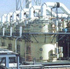
In 1906, Dr. Frederick Cottrell, a professor of physical chemistry at Berkeley, successfully precipitated sulphuric acid fumes in a small electrostatic precipitator (ESP) test unit through the use of a high voltage transformer and the newly-invented synchronous mechanical rectifier. In 1907, Dr. Cottrell and his associates formed the International Precipitation Company for the marketing of his newly invented electrostatic precipitation process. Western Precipitation (WP) was established as a licensee for commercializing the ESP in the state of California. Dr. Cottrell's intent was to establish similar operating companies throughout the Unites States and Canada and then around the world.
The commercial feasibility of the electrostatic precipitator was first demonstrated at a sulphuric acid plant of E.I. DuPont de Nemours Powder Works in Pinole, California, on the San Francisco Bay, where arsenic vapors were impacting the operation of their catalytic converters. The Western Precipitator ESP proved to be the effective solution and with its success, a second installation at the Selby Smelter followed that same year. This installation was designed for the collection of sulphuric fumes escaping from the gold smelting drums and remained in operation for several decades.
The ESP
was also successfully demonstrated at the Riverside Cement Company in Crestmore,
California for the recapture of cement kiln dust.
In 1912,
Dr. Cottrell with the other international patent holders, Sir Oliver Lodge of
England and Dr. Erwin Moeller of Germany, formed the Research Company as a
non-profit patent administrative company in the interest of developing the
electrostatic precipitation process worldwide. This organization
acted as a clearinghouse for process improvements and established operating
territories for the participating companies, which included Western
Precipitation of Los Angeles, Research Corporation of New York, Lodge-Cottrell
of England, Lurgi Apparatebau- Gesellschaft of Germany and Japanese Cottrell
Corp. of Japan.
This international cooperative provided for the accelerated development of the process until World War II when it was disbanded. Western Precipitation, Research Corporation and Lodge-Cottrell, Ltd continued their relationship until the United States government declared that the patent control and the territory distribution violated the Anti-Trust Laws. Consequently, Western Precipitation and Research Corporation entered into a Consent Decree in 1946, under which all territory restrictions were abrogated. Western Precipitation was then free to operate throughout the world.
Western Precipitation was acquired by and became a division of the Joy Manufacturing Company in 1959, where it continued as the world leader in air pollution control technologies, offering a wide range of products for utility and industrial applications in the world marketplace, including Electrostatic Precipitators, Baghouses, Dry FGD systems using NIRO Atomizer technologies, Wet FGD systems, Multiclones and small scrubbers.
In 1987,
Ecolaire's parent, Ecolaire Holding, merged with Joy Manufacturing Company,
leaving Ecolaire as a subsidiary of Joy Technologies Inc. Western
Precipitation combined operations with Allen-Sherman-Hoff (A-S-H), another Joy
unit, forming Joy Environmental Technologies, Inc. (JET).
In 1994, Harnischfeger Industries acquired the stock of Joy Technologies and Joy became a subsidiary of Harnischfeger. In the following year, the Diamond Power Specialty Company, a division of the Babcock and Wilcox Company, a McDermott company, inquired as to the purchase of Joy Environmental Technologies, Inc., anticipating a synergy with its highly successful sootblower and auxiliary boiler equipment business. Following negotiations, Diamond Power Specialty Company (DPSC) acquired the assets of JET on December 20, 1995.
Electrostatic precipitators use electrostatic forces to separate particles from the gas. The discharge electrode, which is normally negatively charged, emits a stream of electrons in the direction of the collecting electrode, which is at zero potential (i.e. earthed). The applied high voltage of 40 to 70 kV is responsible both for the development of the corona and the formation of the electric field between the electrodes.
In the vicinity of the discharging corona the gas becomes ionized. The particles to be separated from the gas, which initially are at different potentials (positive, negative, neutral) are negatively charged because of the bombardment by negative ions and ionic diffusion. In the presence of the electric field the negatively charged particles begin to migrate to the collecting electrode. This migration is impeded by the viscosity of the gas but the electrostatic forces are strong enough to overcome the drag of the gas and the particles proceed to be collected.
The efficiency of an electrostatic precipitator is given by the Deutsch equation:
Collection Efficiency = 1 - exp (-wA/V)
where
w - migration velocity
A - collecting area
V - gas flow
The migration velocity is the average velocity at which the charged particle travels to the collecting electrode. The amount of electrical charge that can be place onto a particle is a function of the size of the particle, gas properties, electrical, chemical and physical properties of the particle as well as the design of the discharge electrode. The migration velocity is generally based on experimental and actual operating data determined from years of experience. Each vendor will have their own database of design velocities which they use when sizing their units.
The magnitude of the migration velocity indicates the difficulty of removal for a particular contaminate. In general, acid mist, copper, iron and nickel are wasy to collect. Zinc, lead, arsenic and antimony are more difficult to collect. For a given gas velocity through the ESP the desired collection efficiency and migration velocity will set the collection area required.
A simple and quick means of determining the performance of a ESP is to check the clarity of the gas leaving the ESP. Most ESP's are equipped with two sight glasses located 180° apart at the exit of the ESP which can be used to check the clarity of the gas. If present, acid mist will appear as a fog. If the operator can see clearly across the gas to the opposite side of the unit, the gas is considered optically clear. This will correspond to an acid mist loading of less than approximately 30 mg/Nm³ (0.84 mg/SCF). When designing a ESP, an acid mist loading of half this value 15 mg/Nm³ (0.42 mg/SCF) is generally used.
All ESP's have basically the same components regardless of the vendor. The ESP's may look all different but they will all have the following components:
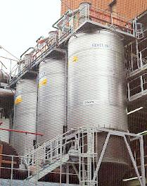
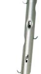
Examples of ESP installations from the different vendors is shown below. The picture in the introduction represents a typical Joy Technologies installation. Joy no longer exist as a company but their technology has been carried on by some vendors.
|
|
|
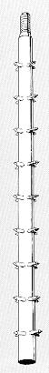
The design of the discharge electrode is one of the major features of an ESP that distinguishes one vendor from another. The discharge electrode must have the following properties to function effectively:
The sharp points or edges are required for the discharge corona to form. Early ESP's were used star wires which were lead covered wires made of steel or alloy 20. The cross-section of the wire is a multi-pointed star shape. The points form a continuous sharp edge running the length of the wire. The wire is support from the upper frame and held taught and straight by a lead weight at the bottom. The grooves running the length of the wire are susceptible to fouling if the units are not regularly flushed and maintained. Occasionally a wire would break and fall to the bottom of the unit. The worst case would be a broken wire that remains hung up in the tube causing an electrical short which would disable the entire unit.
Research into the design and electrical discharge characteristics of the electrodes has resulted in a variety of different designs. The tendency is towards a rigid pole or mast with spikes which is offered by most vendors. The discharge electrode is held at both ends by the support frame on top and the guide frame on the bottom. Both frames are held in position by support insulators attached directly to the shell of the ESP. This ensures that the discharge electrode is always centred.
 |
|
|
|
|
|
||
Southern Environmental |
|||
Electrostatic precipitators come in two basic styles; Plate and Tubular. The majority of wet ESP's are of the tubular design with only a fraction being of the plate design. The traditional style of tube is the circular tube. Early research into electrostatic precipitation determined that the optimum tube diameter was 250 mm (10 in.) This dimension is still the standard for tube size. Many different tube shapes are available each having advantages and disadvantages.
Circular
The advantage of a circular tube is that the distance from a centrally located discharge electrode is the same no matter which direction you travel perpendicular to the axis. Since virtually all ESP's are multi-tube designs, the circular tubes must be arranged in a bundle. The traditional lead tubes were attached to upper and lower tubesheets spaced on a pitch that is generally larger than the diameter of the tube which lead to the major disadvantage of a circular tube. The tubes cannot be nested right next to each other so the diameter of the unit must increase to accommodate the spacing between the tubes. As well, only the inside surface of the tube is utilized as a collecting surface. To overcome the disadvantages of a circular tube, other shapes and designs were developed.
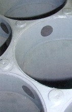
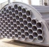
GEA Bischoff (Formerly Lurgi) have developed a round tube design made of PVC in which the tubes are spaced much closer together. The arrangement approaches a hexagon tube design.
Lurgi - PVC Tube Bundle 254 mm (10") round PVC tubes. Close spacing of tubes makes this design more compact than traditional lead tube designs.
Close up of tube
Completed tube bundle (half)Square
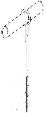
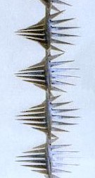
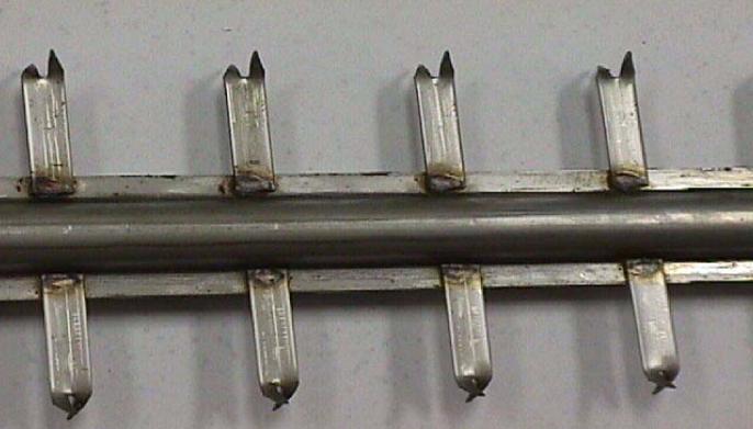
A square shaped collecting electrode allows each tube to be position right next to each other such that adjacent tubes share a common wall leading to a compact ESP. The major design problem that must be overcome is the fact that the distance from the centre of the tube to the corner is larger than the distance to the side wall. To overcome this problems a special electrode design is used. The discharge electrode consist of a rigid post with lead spikes attached to the post. The lead spike are bent in such a way as to extend or point into the corners. This allows the corona that is formed to extend uniformly across the cross-section of the tube.
Hexagon
Hexagons can be nested right next to each other such that there is no dead space between the tubes. Adjacent tubes share a common wall as with the square tubes. The advantage that a hexagon has over a square tube is that it closely approximates a circle. The difference from the centre of the tube to the corner compared to the distance to the side wall is not as great as in a square tube. More 'conventional' discharge electrodes can be utilize and still acheive a uniform corona.
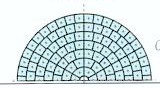
Annular Divided Space
A relatively recent development is an ESP constructed of concentric tubes evenly spaced with the annular space divided into individual tubes by vertical walls. The shape that results is close to a square near the outside of the unit but becomes more pie shaped closer to the centre. Like the square and hexagon tubes adjacent tubes share a common wall so the unit is compact. The outer wall also serves as the shell of the unit. Being a cylinder, no special steps need to be taken to design the unit for high vacuums.