|
||
| Sulphuric Acid on the WebTM | Technical Manual | DKL Engineering, Inc. |
Knowledge for the
Sulphuric Acid Industry
![]()
Sulphuric Acid on the Web
Introduction
General
Equipment Suppliers
Contractor
Instrumentation
Industry News
Maintenance
Acid
Traders
Organizations
Fabricators
Conferences
Used
Plants
Intellectual
Propoerty
Acid
Plant Database
Market
Information
Library
Technical Manual
Introduction
General
Definitions
Instrumentation
Plant Safety
Metallurgial
Processes
Metallurgical
Sulphur Burning
Acid Regeneration
Lead Chamber
Technology
Gas Cleaning
Contact
Strong Acid
Acid Storage
Loading/Unloading
Transportation
Sulphur
Systems
Liquid SO2
Boiler Feed Water
Steam Systems
Cooling Water
Effluent Treatment
Utilities
Construction
Maintenance
Inspection
Analytical Procedures
Materials of Construction
Corrosion
Properties
Vendor Data
DKL Engineering, Inc.
Handbook of Sulphuric Acid Manufacturing
Order
Form
Preface
Contents
Feedback
Sulphuric Acid
Decolourization
Order Form
Preface
Table of Contents
Process Engineering Data Sheets - PEDS
Order
Form
Table of Contents
Introduction
Bibliography of Sulphuric Acid Technology
Order Form
Preface
Contents


Contact Section - Blowers
July 2, 2019
The blower compresses the gas to sufficient pressure to overcome the pressure
drop through the plant. In a sulphur burning acid plant, the gas handled
by the blower is air. In a regeneration or metallurgical acid plant the
gas contains SO2
and traces of acid mist. The gas must be dried in a Drying Tower before
passing through the blower in order to prevent corrosion from acid condensation.
Metallurgical or Regeneration Acid Plant
In a regeneration or metallurgical acid plant, the blower must be positioned after the drying tower in order to ensure that moisture, which could cause corrosion due to acid condensation, is removed from the gas prior to entering the blower.
In a sulphur burning acid plant the blower can be positioned before or after the drying tower. The positioning will depend on the energy recovery requirements of the plant
Positioning the blower before the drying tower (‘pusher’ blower) results in savings in capital cost of the blower because the inlet gas will be more dense and requires less power to compress. The gas being handle is simply air so no special materials of construction are required. However, the heat of compression of the gas is absorbed by the drying acid system thus increasing the heat load on the acid coolers.
Positioning the blower after the drying tower (‘sucker’ blower) maximizes heat recovery and steam production and minimizes acid cooling requirements. The materials of construction for the blower must allow for the fact that the dried air contains traces of acid mist. Better mist eliminating equipment is required in the drying tower to protect the blower when the blower is located downstream. Impaction type candles or a double mesh pad instead of a single mesh pad should be specified.
The operation of an acid plant requires that the flow rate through the blower be varied to meet the production requirements of the plant. There are several different ways to control the flow through the plant.
Inlet guide vanes provide the most efficient method of controlling the blower output when the blower is driven by a constant speed device such as an induction motor. Inlet guide vanes are located directly on the suction flange of the blower and controls the flow through the blower by varying the position of pie-shaped vanes. In the closed position, the pie-shaped vanes block off the area for flow resulting in the minimum flow through the blower. As the vanes are rotated, more gas is allowed to pass through the blower. Guide vanes throttle the flow of gas to the blower suction thus artificially lowering the inlet pressure which lowers the discharge pressure. In addition to throttling the flow, guide vanes also change the inlet gas angle to the impeller, thereby modifying the compressor characteristic curve.
The turndown of the blower is limited to about 35% of maximum flow with inlet guide vanes. Lower flows can be achieved with the use of a recycle line from the blower discharge to the blower suction.
A blower with a variable speed motor is more expensive than a blower with inlet guide vanes. A variable speed motor offers potential savings in power consumption, particularly if the plant throughput varies frequently. A variable speed motor driven blower gives more operating flexibility and lower turndown than a system with inlet guide vanes.
One disadvantage of variable speed motors is that they may not be available beyond a certain size (i.e. horsepower).
Variable speed motors are sometimes referred to as variable speed drives (VSD) or variable frequency drives (VFD).
A steam turbine driven blower makes use of steam generated by the acid plant (particularly sulphur burning acid plants). As with a variable speed motor driven system, there are potential savings in power consumption, lower turndown, and greater operating flexibility than a motor driven blower with inlet guide vanes. Flow through the blower is varied by varying the speed of the turbine and hence the blower.
Variable Speed Transmission or Gear Box
The flow through the plant can be controlled by using a variable speed transmission or gear box to vary the speed of the blower. This option introduces a complex mechanical device into the blower train. The variable speed transmission or gear box is generally driven by a constant speed motor.
Electric Motor versus Steam Turbine
The main acid plant blower is generally driven by either an electric motor or steam turbine. The decision to use one or the other depends on many factors. Some factors that must be considered are:
Traditionally, sulphur burning acid plants without co-generation have used steam turbines to drive the main blower. In this case, high pressure steam has no value other than to drive the main blower. Generally, the steam turbine exhausts the steam at a lower pressure that is suitable for use in the fertilizer complex . Excess high pressure steam is letdown to a lower pressure, condensed or vented. The steam turbine will typically operate at an efficiency of 60 to 65%. Steam turbines that are 70 to 75% efficiency can be utilized but the capital cost of the unit is more.
If an acid plant has a co-generation facility, the economics of the situation change. In this case, the high pressure steam has a value equal to the electric power that is generated. All the high pressure steam is sent to a turbogenerator to generate electric power. The turbogenerator operates in the region of 80% efficiency. Low pressure steam can be extracted from the steam turbine casing for process use. The remaining steam is fully condensed and the condensate recycled. The blower is driven by a synchronous electric motor operating at 90 to 95% efficiency.
Overall, when all factors are considered, the electric motor driven option comes out ahead of the steam turbine option in most cases.
Surging or pumping represents an unstable condition of flow. It occurs when the inlet volume of a blower is reduced to a value less than the volume corresponding to the maximum discharge pressure attainable at the particular speed or inlet guide vane position at which the unit is operating. Conversely, surging can also occur when restrictions in the system increase the back pressure to a value greater than the maximum discharge pressure attainable with the associated inlet volume. When this occurs, a point is reached where the back pressure is greater than the pressure ration the blower is capable of developing at that flow. This causes a reversal in flow through the blower to reduce the blower back pressure. As soon as this reversal occurs, regular compression is resumed and the cycle is repeated. The rapid oscillation of inlet flow is known as surging.
Surging is undesirable since it may result in damage to the blower and downstream equipment. The reversal of flow through the blower may cause excessive vibration in the unit. Each time the gas oscillates through the blower, it gets heated and the resulting temperature increase of the gas and blower may result in damage to the impeller and casing. The oscillations in gas flow also creates pressure waves in the downstream ducting and equipment. The high forces created by these pressure waves can damage equipment particularly expansion joints within the ducting.
If a surge condition occurs the system must be checked immediately for restrictions in the blower suction or discharge (i.e. closed damper). Removing this restrictions should bring the blower out of the surge condition. If the restriction cannot be removed, the blower must be shutdown immediately to prevent damage to the blower and downstream equipment.
Surge detection systems can be employed to detect when the blower is approaching a surge condition. Many of these systems work by entering the surge curve into a program and then measuring blower operating parameters such as flow, pressure and temperature to determine where the blower is operating relative to the surge curve. If the operating conditions approach the surge curve, an alarm is raised and if the blower enters the surge condition, the unit can be shutdown before damage can occur.
Another method of preventing surge is the use of a recycle line or “blow off”. In an acid plant a “blow off” is not practical since the gas will contain SO2. A recycle line from the blower discharge back to the inlet of the drying tower is a common feature of many acid plant. If the blower enters a surge condition, the recycle line is opened effectively increasing the flow through the blower which brings the blower out of the surge condition. The opening of the recycle line can be tied to the surge detection system discussed previously or can be operator initiated. The recycle line is directed back to the inlet of the drying tower so the heat of compression can be removed prior to recycling the gas back to the blower suction. This prevents over heating of the gas and the blower.
|
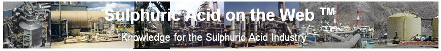
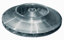
Open radial bladed impellers are ideally suited for dirty gas, corrosive or high head applications. Their inherent self-cleaning design permits longer operation on dirt-laden or corrosive gas service without shutdown. At a given tip speed, higher heads are possible than with other impeller designs. A wide variety of materials are available to meet special application needs. Radial bladed impellers have a relatively flat head-volume characteristics, thus permitting a wide variation in volume with little change in pressure. The efficiency is almost constant over the normal range of operation. As a result, the power requirements are proportional to flow. |
|
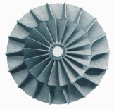
Open impellers with back-leaning blades combine the features of both the radial bladed type and enclosed type with back-leaning blades. They have moderately rising head-volume characteristics, which not only permit a wide range of flows in a given impeller but also allow a moderate variation in pressure. Efficiency is greater than that of a radial bladed type. The power-volume characteristics rises with flow at a rate slightly less than that of the radial bladed type. |
|
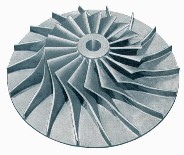
Enclosed impellers with
back-leaning blades are extremely useful in applications that require a
steep head-volume characteristic as well as the highest attainable
efficiency. Applications include parallel operation with other compressors,
or boosting of another compressor's output. Enclosed impellers are also
used for process recycle service or in applications requiring high
efficiency to reduce overall energy costs. The power-volume curve will show a self-limiting feature at higher volumes. This feature is very beneficial when the driver has limited power available but operation throughout the full capacity range is required. |
The shaft of the blower must be seal at the point the shaft exits the casing to prevent the escape of process gas. There are many different types of sealing arrangements but the simplest effective sealing arrangement is the split carbon ring type. An air purge may also be employed to minimize the escape of process gas. The housing of the shaft seal should be flanged to the rear cover of the casing and be horizontally split to allow for easy inspection and replacement of the carbon rings.
Blowers are equipped with two types of bearings; Radial and Thrust bearings.
Radial bearings carry the weight of the shaft and impeller and provides for their free rotation. Radial bearings for sulphuric acid plant blower applications are generally pivoted shoe oil flooded or sleeve type bearings.
Thrust bearings carry axial forces on the shaft created by the rotating impeller.
 |
Pivoted shoe bearings consist of multiple pivoting shoe pads equally spaced around the base of a horizontally split bearing body. Each shoe is self-aligning to compensate for shaft angularity. A separate oil film is formed between each shoe and the shaft journal. The bearings are designed for easy inspection and maintenance, and can be removed without disturbing the shaft. Pivoted shoe bearings are used on heavy duty machines where rugged and reliable service is required. |
 |
Sleeve type radial bearings are generally for moderate duty applications. The bearings is horizontally split which allows the bearings to be removed for inspection and maintenance without disturbing the shaft. |
 |
Thrust bearings are generally tilt-pad, double-acting bearings which will accept thrust forces in either direction along the shaft. The bearing utilizes a number of tilting[pad shoes on either side of the thrust collar. A separate oil film forms between each shoe and the thrust collar that is proportional to the speed and loading. The thrust bearing is self-adjusting so that the thrust load is equally divided among the shoes on either side. The bearings also compensate for minor misalignment or deflection of the bearing housing or shaft. |
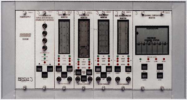
Large, high speed rotating equipment must be protected from excessive vibration and temperatures, otherwise they will not give reliable and continuous service and may fail, sometime catastrophically. A monitoring system provides for continuous monitoring of vibration and temperature and has the ability to shutdown the machine if preset limits are exceeded.
Monitoring of bearing temperatures are important since high temperatures can lead to bearing failure. Typically each bearing on the blower, gear box and driver will be equipped with an RTD for temperature monitoring.
The following is the minimum requirement for temperature monitoring:
Monitoring of vibration is also critical. High vibrations occur because of an out of balance condition somewhere in the equipment. For the blower it is generally caused by a build-up or deposits on the impeller.
The following is the minimum requirement for vibration monitoring:
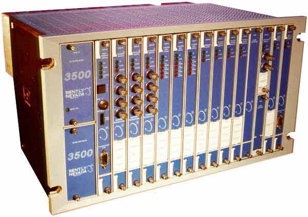
Bentley Nevada produces a monitoring system that is commonly used for equipment monitoring. For many years the 3300 system was the standard for the industry. The 3300 is now being phased out in favour of the new 3500 system.
|
|