|
||
| Sulphuric Acid on the WebTM | Technical Manual | DKL Engineering, Inc. |
Knowledge for the
Sulphuric Acid Industry
![]()
Sulphuric Acid on the Web
Introduction
General
Equipment Suppliers
Contractor
Instrumentation
Industry News
Maintenance
Acid
Traders
Organizations
Fabricators
Conferences
Used
Plants
Intellectual
Propoerty
Acid
Plant Database
Market
Information
Library
Technical Manual
Introduction
General
Definitions
Instrumentation
Plant Safety
Metallurgial
Processes
Metallurgical
Sulphur Burning
Acid Regeneration
Lead Chamber
Technology
Gas Cleaning
Contact
Strong Acid
Acid Storage
Loading/Unloading
Transportation
Sulphur
Systems
Liquid SO2
Boiler Feed Water
Steam Systems
Cooling Water
Effluent Treatment
Utilities
Construction
Maintenance
Inspection
Analytical Procedures
Materials of Construction
Corrosion
Properties
Vendor Data
DKL Engineering, Inc.
Handbook of Sulphuric Acid Manufacturing
Order
Form
Preface
Contents
Feedback
Sulphuric Acid
Decolourization
Order Form
Preface
Table of Contents
Process Engineering Data Sheets - PEDS
Order
Form
Table of Contents
Introduction
Bibliography of Sulphuric Acid Technology
Order Form
Preface
Contents

Contact Section -
Blowers
- Lube Oil Systems
July 18, 2003
|
Introduction Oil Pumps Oil Filters Oil Piping Oil Reservoir Lube Oil Coolers Pressure Control Lube Oil Specification Lube Oil System Flushing Instrumentation |
Associated Links |
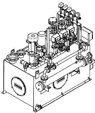
Lube oil systems provide lubrication and cooling to the rotating parts and bearings of the blower, gear box and driver. Lube oil systems for acid plant blowers are generally forced oil systems consisting of a main oil pump, standby oil pump, oil reservoir, duplex oil filters, oil coolers, instrumentation and piping.
Oil pumps are generally positive displacement gear type pumps. On motor driven blowers, the main oil pump is generally driven off the low speed side of the gear box. The auxiliary oil pump is generally electric motor driven. A rundown oil pump is sometimes specified to ensure the bearings are supplied with oil when the plant and blower shutdowns due to a site electrical power failure. The rundown oil pump will be motor driven with power supplied by a uninterruptible power supply (UPS). Alternatively, the auxiliary motor driven oil pump can be supplied by the plant emergency power system.
During normal operation the main oil pump circulates oil from the reservoir, through the oil filters and to the bearings and gearbox. In the event of a main oil pump failure the oil pressure will decrease and a low oil pressure switch will start the auxiliary oil pump.
Oil filters remove contaminates such as dirt, scale, etc. from the lube oil to prevent damage to the blower and driver bearings. Two oil filters are generally specified with one operating and one standby. Flow valves must enable the flow to be switched from one oil filter to the other without interruption in the flow of oil to the equipment. The flow valves must also enable the off-line filter to be replaced without interrupting the operation of the blower.
Oil filters generally filter the oil down to a minimum of 25 µm. Some manufacturer’s required filtration down to 10 µm.
The oil piping supplied oil to the bearings and gear box and returns the oil to oil reservoir. The oil supply piping downstream of the oil filters is generally stainless steel to avoid the formation of scale or rust which will damage the bearings. Oil return piping can be carbon steel.
All new piping must be thoroughly cleaned and pickled prior to installation. The piping is further cleaned when the oil system is flushed.
The oil reservoir is a tank in which the oil returning from the bearings and gearbox collects and from which oil is pumped to the system. The oil reservoir is generally an rectangular carbon steel tank sized for a minimum of 3 minutes retention time from the pump suction to the minimum operating level.
The oil reservoir should be equipped with a low point drain, level gauge, dip stick, vent, and access hole for cleanout and inspection.
An immersion type electric oil heater is required to preheat the oil during initial start-up so the oil system is flushed with oil near its normal operating temperature. An oil heater may also be required for operation in cold climates. The oil heater is protected by a low oil level switch in the oil reservoir.
Lube oil coolers are conventional shell and tube heat exchangers with water on the tube side and oil on the shell side. Water is placed on the tube side for ease of cleaning.
The oil pressure on the cooler should be higher than the cooling water pressure to ensure that oil will leak into the water side and not vice versa.
Pressure control in the oil supply header is generally maintained by a back pressure regulator type valve which returns a portion of the pump output back to the reservoir. This allows the required oil flow and pressure to pass onto the system.
The oil used in lube oil systems must meet certain requirements in order to provide proper lubrication to the rotating parts of the machine. Each equipment manufacturer will have specific requirements for the type and quality of oil required for their system. Some vendors will specify a specific oil type and supplier while others will give general oil requirements/properties that must be satisfied and leave the selection of the specific oil up to the equipment owner. The following are general oil requirements:
The oil should meet the requirements of API Standard 614.
All lube oil systems should be thoroughly flushed after initial installation and after major work on the system. The importance of this step cannot be over-emphasized. All dirt, rust, scale, weld slag, or other contaminants that have been introduced into the system during fabrication, transportation, storage, assembly must be removed by flushing the system. In some cases mechanical cleaning, pickling and neutralization may be required to ensure a clean system.
Flushing should begin as soon as the system is assembles and oil can be circulated through the system. Flushing should continue until inspection of the filters indicates that all contaminates have been removed.
The following provides general points to be consider for lube oil system flushing. Vendor instructions for flushing should be followed.
Instrumentation is provided to control the oil system, to alarm at predetermined variations from normal conditions, and to trip the machinery when the abnormal conditions approach damaging values. Pressure and temperature indicators, liquid level glasses and sight flow indicators provide operators with visual operating information necessary to manually correct for abnormalities in oil temperatures, filter fouling, low oil levels, etc.
Pressure
Lube oil pumps discharge - Local gauge
- Low pressure alarm (start auxiliary pump)
- Low/low pressure trip (blower shutdown)
- High pressure switch (blower start permissive)Lube oil filters discharge - Local gauge Lube oil filter differential pressure - Pressure switch
Temperature
Lube oil cooler outlet - Local gauge and remote indication Drains from each bearing - Local gauge Lube oil cooler inlet - Local gauge and remote indication Lube oil filter outlet - High temperature switch
- High/high temperature switchLube oil reservoir - High temperature switch
Level
Lube Oil Reservoir - Local level sightglass
- Low level alarm
- Low-low level alarm (shutdown oil heater)
Flow
Lube oil to each compressor bearing - Local flow indicator Lube oil to gear box - Local flow indicator Lube oil to driver - Local flow indicator Lube oil from compressor - Local flow sight glass Lube oil from gear box - Local flow sight glass Lube oil from motor - Local flow sight glass