|
||
| Sulphuric Acid on the WebTM | Technical Manual | DKL Engineering, Inc. |
Knowledge for the
Sulphuric Acid Industry
![]()
Sulphuric Acid on the Web
Introduction
General
Equipment Suppliers
Contractor
Instrumentation
Industry News
Maintenance
Acid
Traders
Organizations
Fabricators
Conferences
Used
Plants
Intellectual
Propoerty
Acid
Plant Database
Market
Information
Library
Technical Manual
Introduction
General
Definitions
Instrumentation
Plant Safety
Metallurgial
Processes
Metallurgical
Sulphur Burning
Acid Regeneration
Lead Chamber
Technology
Gas Cleaning
Contact
Strong Acid
Acid Storage
Loading/Unloading
Transportation
Sulphur
Systems
Liquid SO2
Boiler Feed Water
Steam Systems
Cooling Water
Effluent Treatment
Utilities
Construction
Maintenance
Inspection
Analytical Procedures
Materials of Construction
Corrosion
Properties
Vendor Data
DKL Engineering, Inc.
Handbook of Sulphuric Acid Manufacturing
Order
Form
Preface
Contents
Feedback
Sulphuric Acid
Decolourization
Order Form
Preface
Table of Contents
Process Engineering Data Sheets - PEDS
Order
Form
Table of Contents
Introduction
Bibliography of Sulphuric Acid Technology
Order Form
Preface
Contents

Strong Acid System - Mist
Eliminators - Mesh Pads
July 4, 2001
|
Introduction Design and Sizing Construction Installation Vendors |
Additional
Links
Koch-Otto York |
Knitted wire mesh mist eliminators were first developed by York in the mid 1940's. Wire diameter, size of wire loops and amplitude of crimp are the principal variables that can be controlled to produce different mesh densities and specific surface areas.
Mesh pads are almost always installed in the
horizontal position with gas flowing vertically upwards through the pad.
One notable exception is the York Type S pad which utilizes an angled pad.
A relatively recent development in the design of mesh pads is the composite pad. The mesh is a combination of one or more materials, often a metal alloy and a ultra-high-efficiency fluorocarbon monofilament. The composite-knit or co-knit provides high surface area and void volume, and increased mist removal efficiency in the 1-3 micron particle size range which were not previously capture with older designs.
The design velocity for a given application is the value that produces the best performance in terms of collection efficiency and avoiding flooding and re-entrainment. The Souders-Brown equation is used to determine the design gas velocity through a mesh pad.
V = K (( rL - rG) / rG ) ^ 0.5
where V -
Design gas velocity (ft/s)
K
- Capacity factor
rL
- Liquid density
rG
- Gas density
A mesh pad can operate effectively over a range of 30 to 120% of the design gas velocity. A value representing 100% of the calculated design gas velocity can be used if there is no requirement to handle increased gas flows in the future. A lower gas velocity may be selected if the pad is being sized for future expansion of capacity.
The capacity factor 'K' is a function of the style of mesh and the process conditions. Its value indicates the mesh pad's ability to drain the captured liquid and prevent re-entrainment. A high surface are mesh handling a high vicosity liquid would require a lower 'K' value because these factors will tend to hinder drainage of liquid from the pad. A liqud with low surface tension would tend to be more easily re-entrained so a lower 'K' value is warranted. A mesh pad designed to drain liquid more effectvely would result in a higher 'K' value and hence higher design velocity.
For a sulphuric acid plant application, a 'K' value of 0.35 is typically found in the literature. A higher 'K' value of 0.42 is typical for the high capacity type mesh pads which feature some method for enhancing the draining of the captured liquid from the pad. A lower 'K' value (i.e. < 0.35) is typical for a co-knit mesh pad sue to the higher surface area contained in the mesh.
Once the design velocity is calculated a value the surface area of the pad can easily be determined by dividing the volumetric gas flow by the selected gas velocity.
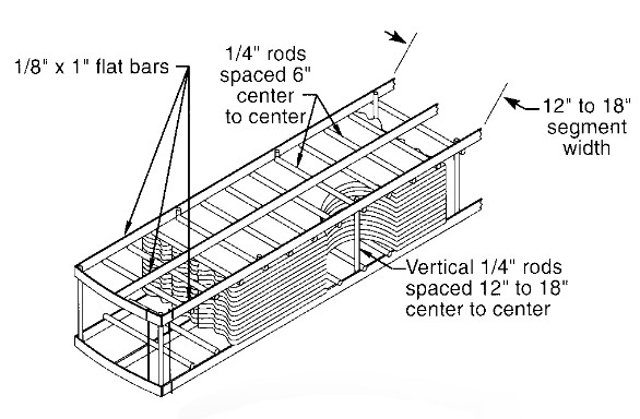
A mesh pad is comprised of metal or plastic monfilaments knitted in a tubular form. The diameter of the monofilaments ranges from 0.006 to 0.011 inches. The tube is flattened to form a two-layer strip ranging in with from 12 to 18 inches. The strip is thne crimped with diagonal corrugations. The crimped strips are then stacked on top of each other to a thickness of 4 to 6 inches to form a typical mesh pad. To add rigidity to the pad, the mesh is stiffened by an upper and lower grid connected by rods running through the mesh.
Composite knit or co-knit mesh pads have a fine monfilament or multifilament yarn knitted with the primary mesh. Co-knit materials influde PTFE, Kynar®, Dacron®, polyproplene and fibreglass. The primary mesh support and prevent compaction of the finer strands.
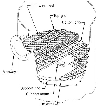
Mesh pads are always slightly oversized so that a tight fit is acheived to eliminate gaps between section of pads and between the pad and the wall of the vessel. An annular support ring is required which will support the edge of the mesh pad. Intermediate supports may be required for larger installations where multiple sections are required to span the width of the vessel.
The mesh pad is equipped with support grids but these are of light weight construction and are not designed to support the weight of a person. Never walk on top of the mesh pad as they are not designed to support the weight of a person and damage to the mesh pad may occur which may affect performance.
In general, installation begins at the ends and sections are installed working towards the centre of the vessel. The last section may be difficult to fit in due to the oversized sections. Use two pieces of sheet metal the length of the section as guides. When the last section is in place remove the sheet metal pieces.
The pad must be secured in position to prevent the
pad from lifting during surging gas conditions. A number of different
methods are used depending on the vendor and the type of installation. 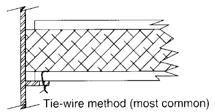
The most common method is the use of tie wires which are attached to the lower support grid and are secured to the annular support ring and beams. These are installed from the underside of the mesh pad.
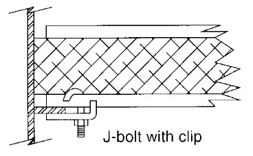
J-bolts with a clip may also be employed which clamp the lower support grid to the support structure. These are installed from the underside of the mesh pad.
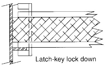
Another common method is to utilize a latch-key lock down device. The latch-key is rotated until the lower 'latch' engages the support ring. A blt is then tightened from above which secures the latch-key in position. The advantage of this method is that all the work is done from the top side of the mesh pad.
The principal vendors of mesh pads to the sulphuric acid industry are:
1. Koch-Otto York
2. Begg Cousland
3. Monsanto Enviro-Chem Systems
4. Kimre
5. ACS Industries, Inc.